

The manual Cast Iron Machine represents a fundamental category of industrial equipment that combines the enduring strength of cast iron construction with the direct, hands-on control of a human operator. Unlike their automated or computer numerical control counterparts, these machines rely entirely on the skill, feel, and judgment of the person operating them. This class of machinery includes a wide variety of tools, from the manual lathe and the milling machine to the drill press, the hand-operated press, and various types of bending and shearing equipment. The defining characteristic is that every movement of the cutting tool, every application of pressure, and every adjustment of the workpiece is initiated and controlled by the operator through mechanical levers, handwheels, foot pedals, or direct physical force.
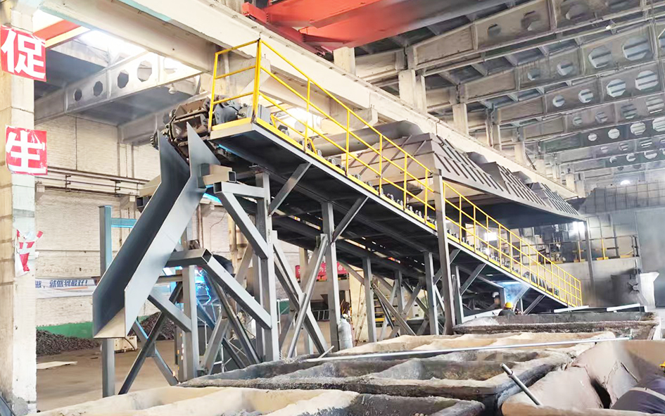
The use of cast iron as the primary construction material for these manual machines is no coincidence. The material's inherent mass provides the stability and rigidity that are essential for accurate hand operations. When an operator turns a handwheel to advance a cutting tool into a workpiece, the cast iron frame absorbs the resulting cutting forces without flexing or deflecting. This lack of deflection is what allows the operator to achieve precise dimensions and fine surface finishes. Furthermore, the natural vibration-damping properties of cast iron are particularly valuable in a manual context. Without the sophisticated electronic feedback systems found in modern machines, a manual machine must rely on its physical structure to absorb and dissipate the vibrations generated during cutting. A cast iron bed or column accomplishes this task admirably, providing a smooth, stable platform that gives the operator confidence and control.
The enduring appeal of the Manual Cast Iron Machine in a world increasingly dominated by automation lies in its simplicity, versatility, and the unique connection it creates between the operator and the work. These machines are capable of producing a vast range of parts, from simple shafts and bushings to complex, custom components. The operator can feel the cutting action through the handwheels and levers, sensing changes in material hardness or tool sharpness that would be invisible to a computer. This tactile feedback allows for real-time adjustments that can improve quality and prevent tool breakage. For small-batch production, one-off prototyping, and repair work, the manual cast iron machine is often the most efficient and practical choice.
Material and Construction
The cast iron used in manual machines is almost exclusively gray cast iron, chosen for its exceptional compressive strength, wear resistance, and vibration damping. The specific grade of gray cast iron, such as those standardized by various material designation systems, is selected based on the required mechanical properties and the complexity of the casting. The base of a manual lathe, for example, is a massive, heavily ribbed casting designed to maximize rigidity while minimizing the amount of material used. These internal ribs are a hallmark of good cast iron design, providing a framework that distributes stresses evenly across the structure.
The process of manufacturing a manual cast iron machine begins with the creation of a pattern, which is a replica of the desired part. This pattern is used to form a cavity in a molding material, typically sand mixed with a binder. The molten gray cast iron, heated to a temperature of approximately 1400 degrees Celsius, is then poured into this cavity. As the iron cools and solidifies, it takes the shape of the cavity. The graphite flakes that form during this solidification process are what give the material its unique damping and lubricating properties. After the casting has cooled, it is removed from the mold, and the various machined surfaces, such as the lathe bed ways or the milling machine table, are finished to precise tolerances.
The quality of the casting is of paramount importance. Defects such as blowholes, sand inclusions, or cold shuts can weaken the structure and compromise its performance. Therefore, reputable manufacturers employ rigorous quality control procedures, including non-destructive testing techniques like dye penetrant inspection or magnetic particle inspection, to detect any internal or surface flaws in the casting before it is machined and assembled. The foundry process is an art as much as a science, and the skill of the foundry workers in controlling the pour temperature, the cooling rate, and the quality of the molding sand all contribute to the final integrity of the machine.
Application Scenarios
The application of manual cast iron machines is vast and varied, ranging from small job shops and educational institutions to large manufacturing plants and maintenance facilities. Their versatility and reliability make them suitable for a wide spectrum of tasks. They are not relics of the past but are actively used alongside advanced manufacturing technologies to fulfill critical roles that automation cannot easily replicate.
In the job shop environment, the manual cast iron machine is the backbone of production. These shops are characterized by small batch sizes, a high variety of parts, and frequent engineering changes. A manual engine lathe is used to turn shafts, threads, and tapers, while a manual milling machine creates slots, keyways, and complex contours. The operator can quickly set up a new job without the need for time-consuming programming, and they can make adjustments on the fly to accommodate variations in incoming material. This flexibility is invaluable for companies that produce custom parts for clients in industries such as aerospace, medical devices, and specialty automotive, where the requirements are often unique and the production runs are short.
In maintenance, repair, and overhaul operations, manual cast iron machines are indispensable. Industrial facilities often have their own machine shops to repair broken components, modify existing parts, or create temporary replacements to keep production lines running. For example, a manual lathe in a steel mill might be used to re-machine a worn shaft on a large rolling mill, saving the plant the cost and downtime associated with ordering a new part. In a shipyard, a manual milling machine can be used to prepare damaged deck fittings for welding repairs. The ability to perform such work in-house, without waiting for external suppliers, is a significant operational advantage that manual cast iron machines provide.
The educational sector is another major area where manual cast iron machines are found. Technical schools, trade colleges, and university engineering departments use these machines to teach students the fundamentals of machining. Learning on a manual machine forces students to understand the physics of the cutting process, the importance of tool geometry, and the relationship between speed, feed, and depth of cut. It builds a foundation of practical knowledge that is essential for any engineer or machinist. Students who have mastered manual machining are better equipped to understand and operate more advanced automated systems later in their careers.
In prototyping and research and development laboratories, the manual cast iron machine is a common sight. When an engineer or designer has an idea for a new part, they do not want to wait weeks for a mold to be made or a CNC program to be written. A manual machine allows them to produce a functional prototype quickly and inexpensively. The operator can iterate on the design in real-time, making adjustments as they go. This speed of iteration is critical in the competitive world of product development, where bringing a product to market quickly can be a decisive advantage.
Agriculture and rural industry also rely heavily on manual cast iron machines. Many farms and small rural workshops have a manual lathe and a drill press. These are used to repair broken tractor parts, fabricate custom implements, and maintain irrigation pumps. The machines are often operated in conditions that are less than pristine, where dust and moisture are a constant challenge. The robust and simple nature of a manual cast iron machine makes it ideal for such environments, where complex electronic equipment might fail. The machines can be repaired with basic tools and a supply of spare parts, ensuring that the agricultural operations can continue with minimal disruption.
Operating Instructions
The operation of a manual cast iron machine is a skill that requires both theoretical knowledge and practical experience. Safety is the paramount concern, and it must be integrated into every step of the process. The following instructions outline the general procedures for operating these machines, though the specific details may vary depending on the type of machine and the operation being performed.
Preparation and Safety Inspection: Before any manual machine is started, the operator must conduct a thorough inspection. This begins with the workpiece itself. The material should be free of hard spots, cracks, or foreign objects that could damage the tooling or cause it to bind. The workpiece must be securely mounted in the chuck, collet, or workholding fixture. If the part is irregularly shaped, it may need to be held in a four-jaw independent chuck or on a faceplate, requiring careful indication to ensure it is running true. The cutting tool must be properly sharpened, with the correct geometry for the material being cut. It must also be securely clamped in the tool post or holder. The operator should check that all guards are in place, that the emergency stop button is accessible, and that the workpiece and tool are clear of each other before the machine is started. Proper personal protective equipment, including safety glasses and hearing protection, must be worn at all times.
Starting the Machine and Setting Cutting Parameters: The machine is started by engaging the appropriate drive mechanism. For a lathe, this means starting the spindle motor and selecting the correct spindle speed. The choice of speed depends on the material, the diameter of the workpiece, and the type of tool being used. For example, a low speed is used for high-carbon steel, while a higher speed might be appropriate for aluminum or brass. The feed rate, which is the speed at which the tool moves along the workpiece, is set through a combination of gearbox settings or by manually turning the carriage handwheel. Once the speed and feed are selected, the operator begins the cut by gradually engaging the feed mechanism.
The Cutting Process and Continuous Monitoring: During the cutting process, the operator must remain fully attentive. The feel of the handwheel is a critical source of information. If the tool is taking too heavy a cut, the operator will feel resistance and can back the tool out to prevent stalling the machine or breaking the tool. The operator must also observe the chips being produced. A continuous, even chip indicates a good cutting condition. Discolored or segmented chips may indicate tool wear or incorrect speeds and feeds. The operator must also listen to the machine. A smooth, rhythmic sound is normal, but a squealing or chattering sound indicates vibration or a problem that needs immediate attention. If the workpiece becomes hot, the operator should apply cutting fluid or coolant to maintain tool life and improve surface finish.
Finishing Operations and Measurements: Once the roughing cuts are complete, the operator will take a series of finishing cuts to achieve the final dimensions and surface finish. These cuts are lighter, requiring less force and leaving a smoother surface. Between cuts, the operator must stop the machine to take measurements with micrometers, calipers, or other precision measuring instruments. Accurate measurement is the only way to ensure that the part meets its specifications. It is crucial to measure the part at multiple points to check for taper, concentricity, or other errors. The operator must also clean the part and the measuring tools before taking each measurement to ensure accuracy.
Shutdown and Cleanup: After the operation is complete, the machine must be shut down properly. The spindle is stopped, and the tool is retracted from the workpiece. The operator should remove the workpiece from the machine and clean all surfaces. Chips and swarf should be cleared from the machine bed and the surrounding area. These metal shavings are sharp and can be a hazard. They should be collected in a designated container for recycling or disposal. The operator should then apply a light coat of oil to the machine's guide surfaces to prevent rust. This step is essential for protecting the precision surfaces and maintaining the machine's accuracy for the next use.
Common Questions and Solutions
Operating a manual cast iron machine inevitably leads to questions and challenges. Understanding the common issues and their solutions is a crucial part of a machinist's expertise. The following addresses several frequently encountered problems.
What should I do if my machine is experiencing excessive chatter? Chatter is a self-excited vibration that leaves a patterned, wavy surface on the workpiece. It is one of the most common problems in manual machining. Several factors can cause chatter. The most likely cause is a lack of rigidity in the workpiece, the tool, or the machine itself. To resolve this, the operator should first ensure that the workpiece is as close to the chuck or spindle nose as possible to minimize overhang. For long, slender parts, a center or a steady rest should be used to support the free end. The cutting tool should be as short as possible, with its overhang minimized to reduce deflection. The tool geometry should also be checked; a tool with insufficient clearance angle can rub and cause vibrations. Changing the spindle speed, either increasing or decreasing it, can also help to alter the excitation frequency and eliminate chatter.
How do I deal with a tool that is dulling quickly? Rapid tool wear can be caused by several factors, including improper cutting speed, incorrect feed rate, insufficient coolant, or using the wrong tool material for the workpiece. If the speed is too high, the tool will overheat and wear rapidly. If the feed rate is too low, the tool will rub against the workpiece rather than cut, generating excessive heat. The operator should consult a reference guide to select the appropriate speed and feed for the material. The coolant supply should also be checked. A proper flood of cutting fluid will cool the tool and lubricate the cutting zone, extending tool life. Finally, if the tool material is not suitable for the workpiece, such as using a high-speed steel tool on a very hard alloy, the operator may need to switch to a carbide or ceramic tool.
My workpiece is not concentric. What could be the cause? This problem means that the outside diameter of the part is not running true with the axis of rotation. The most common cause is that the workpiece is not mounted correctly in the chuck. For a three-jaw chuck, the jaws may not be perfectly gripping the part, especially if the workpiece is not perfectly round. In such cases, a four-jaw chuck is often the solution. The operator must then indicate the workpiece, using a dial test indicator, to adjust the jaws until the part is running dead true. Another potential cause is that the machine's own spindle has runout. This can be checked by indicating a known straight test bar in the spindle. If the spindle is out of alignment, the machine may require maintenance or repair by a skilled technician.
Why is my surface finish so poor? A poor surface finish can be caused by a number of factors. The tool nose radius may be too small, or the feed rate may be too high. A larger nose radius and a lower feed rate will generally produce a finer finish. The tool height also matters; if the tool is not set exactly on center, it will produce a poor finish. The operator should use a tool setter or a ruler to check that the tool tip is at the correct height. Additionally, the machine's gibs and bearings may be loose, allowing the machine to move slightly during the cut, which will produce a rough surface. These should be adjusted to the manufacturer's specifications to restore rigidity and precision.
What is the proper maintenance schedule for a manual cast iron machine? Regular maintenance is the key to a long service life. The daily maintenance includes cleaning the machine and lubricating all moving parts. The guide ways, lead screws, and bearings all require clean oil to function correctly. The operator should check the oil levels in any reservoirs and top them up as needed. The weekly maintenance may include a more thorough inspection of the machine's drive belts and electrical connections. The monthly maintenance should include a check of the machine's alignment and the condition of the clutches and brakes. Annual maintenance, which may be performed by an external specialist, should include a full alignment check and recalibration, as well as a detailed inspection of the spindle bearings and gear train. A well-maintained manual cast iron machine can remain accurate and reliable for many decades, often outlasting several generations of electronic equipment.
In summary, the manual cast iron machine is a testament to the enduring value of robust engineering and human skill. Its applications across industry, education, and maintenance are a testament to its versatility, while its operation demands a disciplined, careful, and knowledgeable approach. The common issues faced during its use are predictable and solvable with the right understanding. This class of machine remains a vital and respected part of the manufacturing landscape, connecting the operator directly to the creative and precise act of making things from metal.
This website uses cookies to ensure you get the best experience on our website.
 Español
 Pусский
 العربية
 Tiếng Việt


 WhatsApp
 Phone: